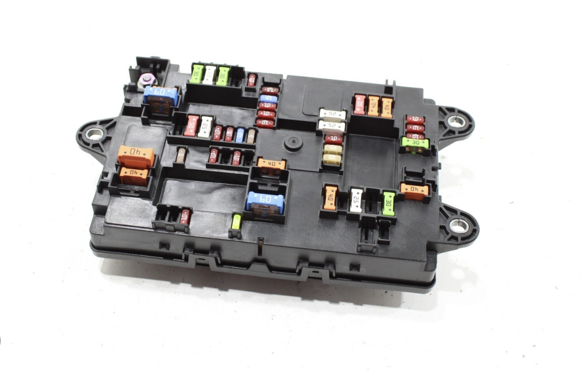
This guide covers the Rivian R1T and R1S fuse box (2022–2024 “Gen 1” models, which share the same cabin electrical layout): where both fuse boxes are located, how to open the panels, a labeled fuse chart, and how to safely check and replace a fuse.
Rivian R1T/R1S Fuse Box Diagram
The R1T and R1S each have two cabin fuse boxes — one in the driver’s footwell and one on the passenger’s side. Click either diagram below to open it full-size and read the layout in detail.
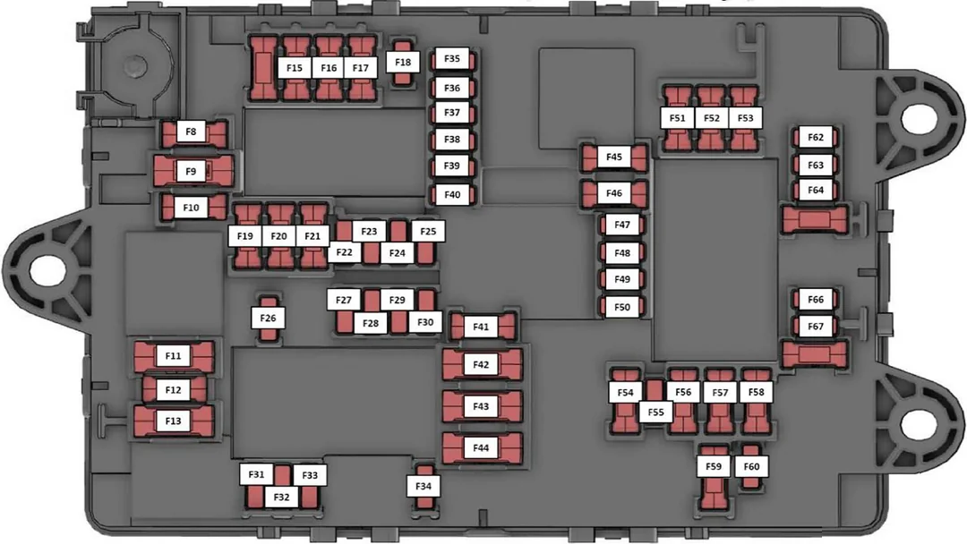
Click to enlarge
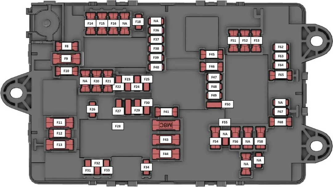
Click to enlarge
Here’s what each fuse box actually looks like once the panel cover is off, so you know what you’re looking at before you go searching for it:
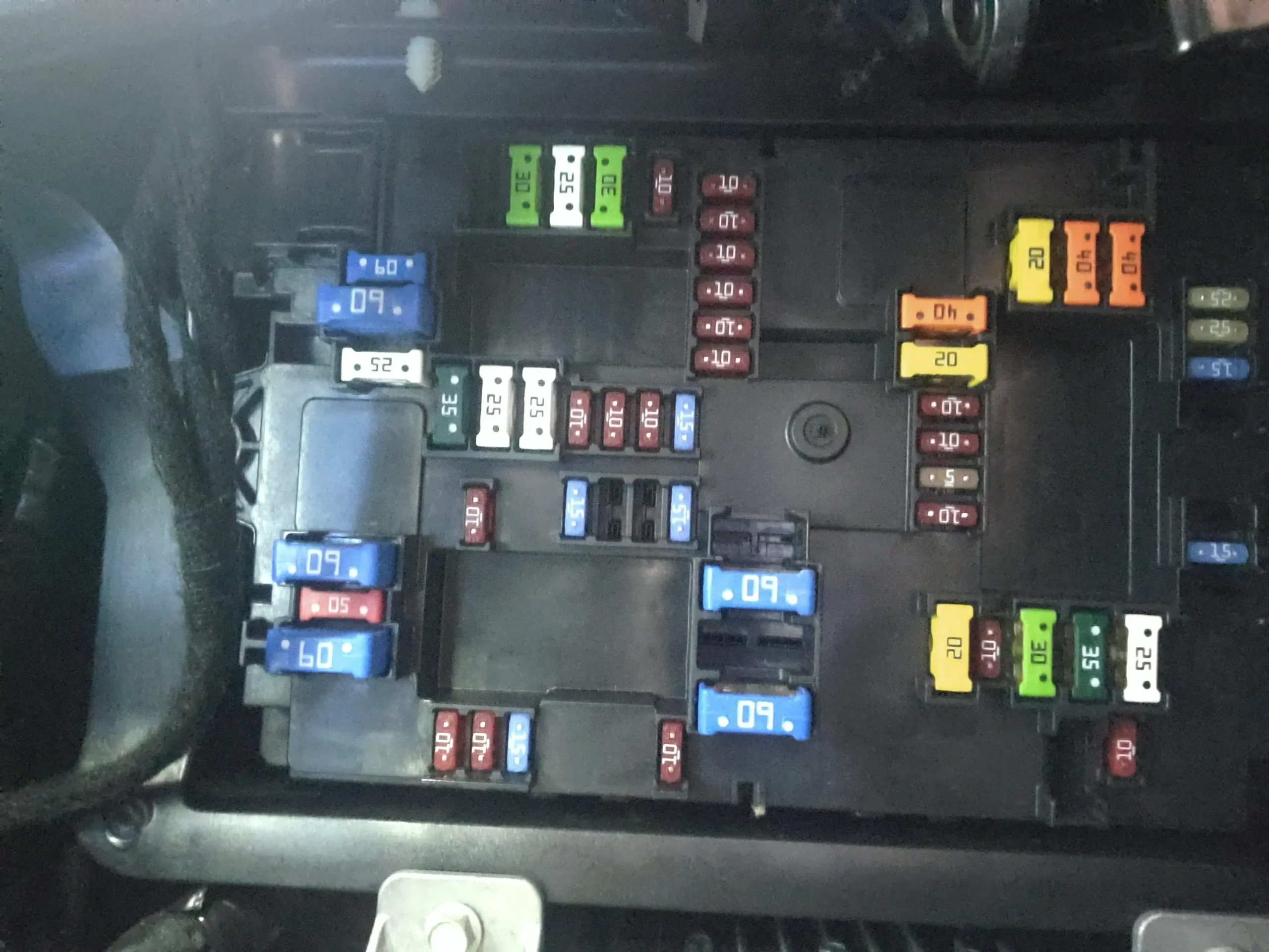
Click to enlarge
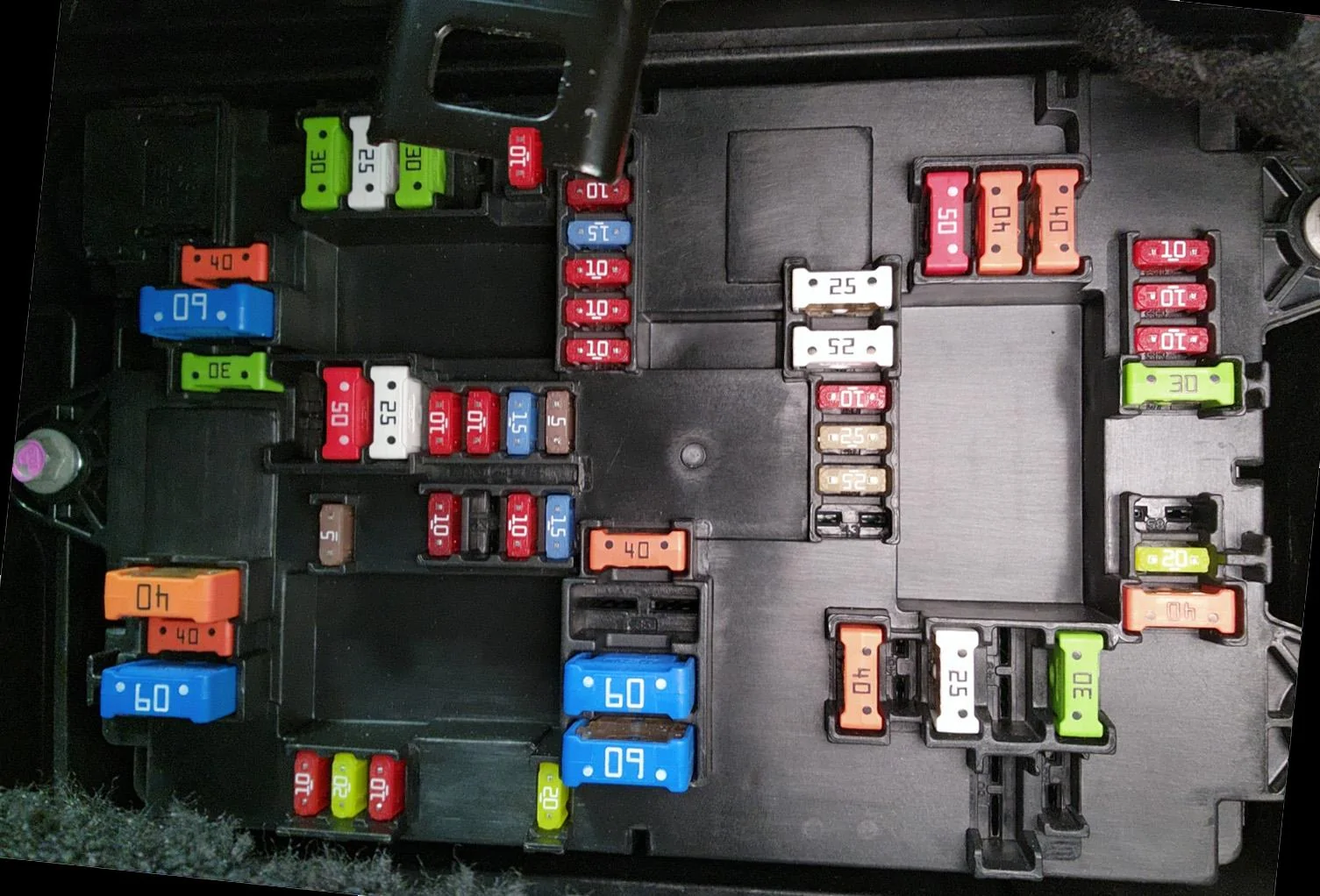
Click to enlarge
Where Is the Fuse Box on a Rivian R1T / R1S?
Because the R1T and R1S share the same Gen 1 cabin platform, the fuse box locations and access steps below are identical on both vehicles. There are two separate boxes, and they are not interchangeable — one lives under the driver’s side dash, the other under the passenger’s side dash.
1. Driver-Side Fuse Box
The driver’s side panel is the one most commonly accessed for dash cam installations or 12V power taps. It sits in the driver’s footwell, above the pedals, behind a plastic kick panel.
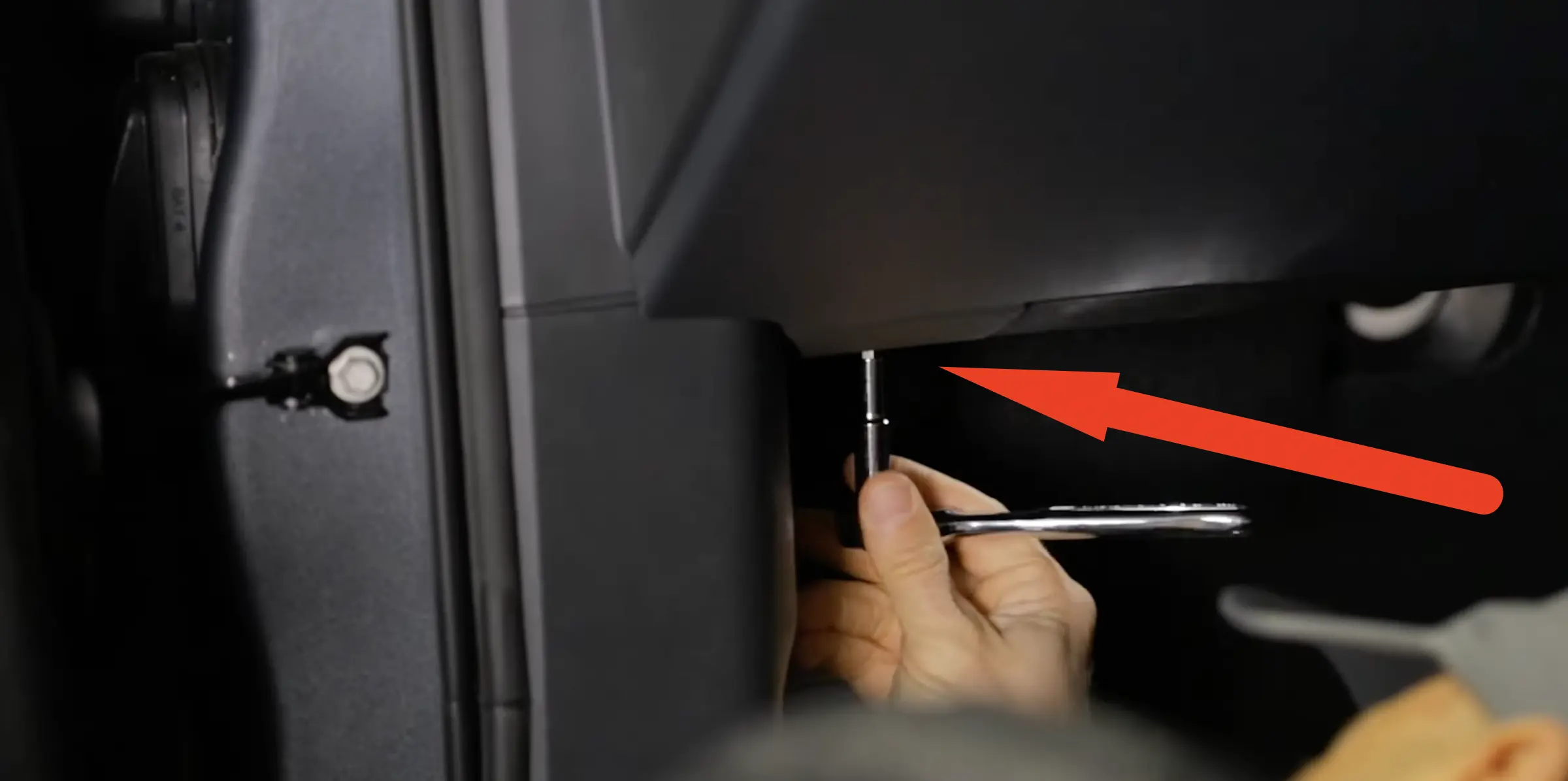
- Locate the screw. Look underneath the dashboard, just above the pedals and driver’s left foot area, and find the single Torx T20 screw.
- Remove the panel. Use a Torx driver to remove the screw. The plastic kick panel is also held by a few retaining clips — gently pull the panel straight down to drop it out of the way.
- Watch for obstructions. Be careful of the attached footwell light and the OBD-II port. You don’t need to fully disconnect them — just let the panel hang down to expose the fuse block behind it.
Click to enlarge
2. Passenger-Side Fuse Box
The passenger-side fuse box is situated further forward, near the firewall, mounted upside-down behind the knee airbag panel.
- Remove the screws. You’ll need to remove two Torx screws securing the panel on the passenger’s side underside.
- Lower the panel. Drop the panel down and carefully disconnect any attached lights to get a clear, unobstructed view of the fuse block.
Fuse Chart: Amperage and Circuit Labels
Rivian doesn’t ship an official printed fuse legend with the R1T/R1S — the numbering below comes from the labeled panel lid itself, cross-referenced with the diagrams pictured in the first section. Always confirm the fuse number against your own panel before pulling anything, since running changes between build dates can shift a circuit to a different slot.
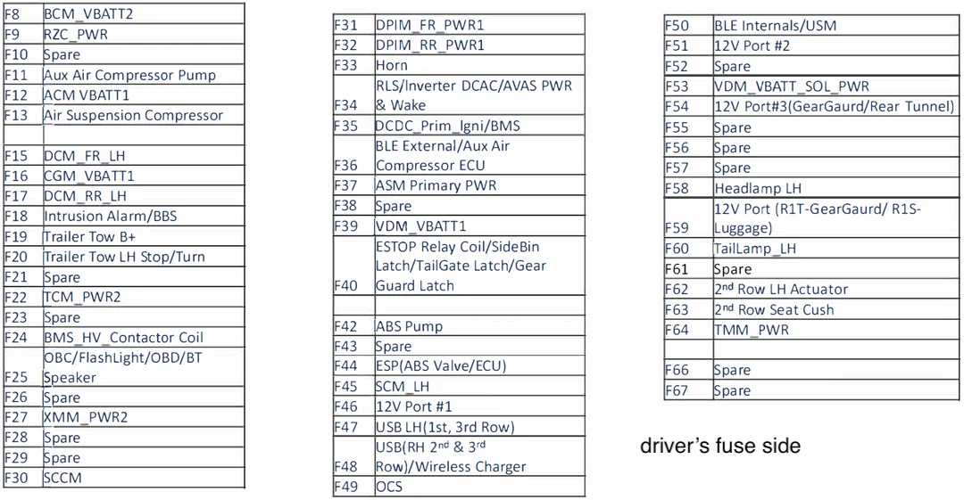
Click to enlarge
- F8 – BCM_VBATT2 (Body Control Module)
- F9 – RZC_PWR
- F10 – Spare
- F11 – Aux Air Compressor Pump
- F12 – ACM VBATT1 (Autonomy Control Module)
- F13 – Air Suspension Compressor
- F15 – DCM_FR_LH
- F16 – CGM_VBATT1 (Central Gateway Module)
- F17 – DCM_RR_LH
- F18 – Intrusion Alarm/BBS
- F19 – Trailer Tow B+
- F20 – Trailer Tow LH Stop/Turn
- F21 – Spare
- F22 – TCM_PWR2 (Telematics Control Module)
- F23 – Spare
- F24 – BMS_HV_Contactor Coil
- F25 – OBC/FlashLight/OBD/BT Speaker
- F26 – Spare
- F27 – XMM_PWR2
- F28 – Spare
- F29 – Spare
- F30 – SCCM (Steering Column Control Module)
- F31 – DPIM_FR_PWR1
- F32 – DPIM_RR_PWR1
- F33 – Horn
- F34 – RLS/Inverter DCAC/AVAS PWR & Wake
- F35 – DCDC_Prim_Igni/BMS
- F36 – BLE External/Aux Air Compressor ECU
- F37 – ASM Primary PWR
- F38 – Spare
- F39 – VDM_VBATT1 (Vehicle Dynamics Module)
- F40 – ESTOP Relay Coil/SideBin Latch/TailGate Latch/Gear Guard Latch
- F42 – ABS Pump
- F43 – Spare
- F44 – ESP (ABS Valve/ECU)
- F45 – SCM_LH
- F46 – 12V Port #1
- F47 – USB LH (1st, 3rd Row)
- F48 – USB (RH 2nd & 3rd Row)/Wireless Charger
- F49 – OCS
- F50 – BLE Internals/USM
- F51 – 12V Port #2
- F52 – Spare
- F53 – VDM_VBATT_SOL_PWR (Vehicle Dynamics Module)
- F54 – 12V Port #3 (GearGuard/Rear Tunnel)
- F55 – Spare
- F56 – Spare
- F57 – Spare
- F58 – Headlamp LH
- F59 – 12V Port (R1T-GearGuard / R1S-Luggage)
- F60 – TailLamp_LH
- F61 – Spare
- F62 – 2nd Row LH Actuator
- F63 – 2nd Row Seat Cush
- F64 – TMM_PWR
- F66 – Spare
- F67 – Spare
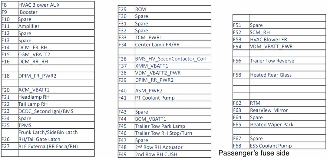
Click to enlarge
- F8 — HVAC Blower AUX
- F9 — iBooster
- F10 — Spare
- F11 — Amplifier
- F12 — Spare
- F13 — Spare
- F14 — DCM_FR_RH
- F15 — CGM_VBATT2 (Central Gateway Module)
- F16 — DCM_RR_RH
- F18 — DPIM_FR_PWR2
- F20 — ACM_VBATT2 (Autonomy Control Module)
- F21 — Headlamp RH
- F22 — Tail Lamp RH
- F23 — DCDC_Second Igni/BMS
- F24 — Spare
- F25 — TPMS
- F26 — Frunk Latch/SideBin Latch RH/Tail Gate Latch
- F27 — BLE External (RR Facia/RH)
- F29 — RCM (Restraint Control Module)
- F30 — Spare
- F31 — Spare
- F32 — Spare
- F33 — TCM_PWR1 (Telematics Control Module)
- F34 — Center Lamp FR/RR
- F36 — BMS_HV_SeconContactor_Coil
- F37 — XMM_VBATT1
- F38 — VDM_VBATT2_PWR (Vehicle Dynamics Module)
- F39 — DPIM_RR_PWR2
- F40 — ASM_PWR2
- F41 — PT Coolant Pump
- F43 — Spare
- F44 — BCM_VBATT1 (Body Control Module)
- F45 — Trailer Tow Park Lamp
- F46 — Trailer Tow RH Stop/Turn
- F47 — Spare
- F48 — 2nd Row RH Actuator
- F49 — 2nd Row RH CUSH
- F51 — Spare
- F52 — SCM_RH
- F53 — HVAC Blower FR
- F54 — VDM_VBATT_PWR (Vehicle Dynamics Module)
- F56 — Trailer Tow Reverse
- F58 — Heated Rear Glass
- F62 — RTM
- F63 — RearView Mirror
- F64 — Spare
- F65 — Heated Wiper Park
- F67 — Spare
- F68 — ESS Coolant Pump
How to Check and Replace a Fuse
Fuse work on the R1T/R1S is straightforward once the panel is open, but Rivian uses a fuse type most owners haven’t handled before.
- Power down first. Turn the vehicle off. For anything beyond a single fuse swap, disconnecting the 12V battery is a good habit to avoid accidental shorts.
- Open the correct panel. Follow the access steps above for the driver’s or passenger’s side, depending on which circuit you’re chasing.
- Identify the fuse. Match the symptom to a circuit using the enlarged legend image, then find that fuse number on the physical panel.
- Pull the fuse. Rivian’s Gen 1 fuse boxes use Italian-made MTA “MaxiCompact”-style fuses — not the blade fuses sold at typical auto parts stores. Use a proper fuse puller rather than pliers to avoid cracking the fuse body.
- Test it. Check continuity with a multimeter or test light. A blown fuse will show an open circuit even though it may look intact visually.
- Replace with the same amperage. Never substitute a higher-amp fuse — it removes the circuit’s overload protection and is a fire risk. Most Rivian owners source MTA MaxiCompact fuses online, or use one of the spare fuses included in the box from the factory.
- Reassemble and test. Clip the panel back into place, reconnect the battery if you disconnected it, and confirm the affected system works again.
Common Fuse-Related Issues
- No factory fuse diagram. Rivian doesn’t include a fuse chart in the owner’s manual, so troubleshooting a blown fuse means relying on community-sourced diagrams like the ones on this page.
- Dead 12V outlets. A non-functional 12V accessory outlet in the gear tunnel, frunk, or cabin is one of the most common complaints, and often traces back to a single blown fuse rather than a bigger electrical fault.
- Hard-to-find replacement fuses. Gen 1 Rivians use MTA “MaxiCompact” fuses, which standard auto parts stores don’t stock. Plan to order online or use the spares provided in the fuse box.
- Multiple unrelated failures at once. If several systems — say, interior lights, radio, and power outlets — quit simultaneously, suspect the fuse box module itself rather than chasing each symptom separately.
- Intermittent faults. Circuits that work, then cut out, then work again point to a loose connector or a marginal fuse rather than a clean failure — worth inspecting the fuse box connectors for corrosion or water intrusion.
- Wipers or power windows dead with a good fuse. If the relevant fuse tests fine but the system still doesn’t work, the fault is likely downstream in the module or wiring, not the fuse itself.
- Burning smell or visible melting. A smell of hot plastic near either footwell, or visible melted plastic/corrosion on the fuse box, means the module itself may be failing and should be inspected before you keep swapping fuses.
- Gen 1 vs. Gen 2 confusion. 2025+ “Gen 2” R1T/R1S models moved to software-resettable eFuses and don’t have these physical fuse boxes at all — this guide and its diagrams apply only to 2022–2024 Gen 1 trucks.